

At the end of this week, the students are expected to:
- Calculate power in a.c circuits containing:
- Resistance
- Inductance
- Capacitance
- Combination of the resistance, inductance and capacitance
1.1 POWER IN A.C CIRCUIT
1.1.1 Power in A.C circuit containing Resistance only+ |
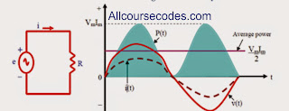
Fig 1.1: (a) pure resistive circuit, (b) power wave form.
(b) Inspection of the power waveform of fig 1.1 shows that its average value lies half way
between zero and its peak value of VmIm. That is P = VmIm/2
Since V (the magnitude of the r.m.s value of voltage) is Vm/√2 and I (the magnitude of the r.m.s value of current) is Im/√2, this can be written as P = VI. Thus, power (average power) to a purely resistive load is P = VI (watts).
(1.1)
Example 1.1: Calculate the power dissipated by the circuit of fig 1.2

Fig 1.2 4
Solution
I = 100V/25- = 4A
- P = VI = 100 x 4 = 400W
1.1.2 Power in A.C Circuit Containing Inductance only
For a purely inductive load as in fig 1.3(a), current lags voltage by 900. A sketch of P versus time (obtained by multiplying V times i) then looks as shown in fig 1.3(b).
Consider fig 1.3. Energy stored during each quarter-cycle is returned during the next quarter cycle. Thus, the average power is zero. Consequently, the only power flowing in the circuit is reactive power. This is given by QL = VI (VAr) (1.2)
Example 1.2: For the circuit of fig 1.4, determine the reactive power

Solution Fig 1.4
I = 100V/20- = 5A
- QL = VI = 100 x 5 = 500VAr

Fig 1.5: (a) pure capacitive circuit (b) power waveform for a pure capacitive circuit. Consider fig 1.5. Energy stored during each quarter-cycle is returned during the next quarter cycle. Thus, the average power is zero. Consequently, the only power flowing in the circuit is reactive power. This is given by
QC = I2 XC
(1.3)
Example 1.3: With regard to fig 1.6, determine average and reactive power.


1.1.3 Power in A.C circuit containing capacitance only
For a purely capacitive load current leads voltage by 900. Multiplications of V times i yield the power curve of figure 1.5
Fig 1.5: (a) pure capacitive circuit (b) power waveform for a pure capacitive circuit. Consider fig 1.5. Energy stored during each quarter-cycle is returned during the next quarter cycle. Thus, the average power is zero. Consequently, the only power flowing in the circuit is reactive power. This is given by
QC = I2 XC
(1.3)
Example 1.3: With regard to fig 1.6, determine average and reactive power.

Fig 1.6 |
Solution
I = 100V/40- = 2.5A.
QC = VI = 100 x 2.5 = 250VAr.
P = 0W.
1.1.4 | Calculations of power in A.C circuits containing R, L and C |
Example 1.4: | For the RL circuit of figure 1.7, I = 5A. Find the power and reactive power. |

Fig 1.7 | |
Solution
22
P = IR = (5) (3) = 75W
QL = I22
XL = (5) (4) = 100VAr
Example 1.5: For the RC circuit of figure 1.8, determine the power consumed and the reactive power.

Fig 1.8 | |
Solution
22
P = V/R = (40)/20 = 80W
QL = V2/XC = (40)2
/80 = 20VAr
Social Plugin