

Three Phase Systems
- Explain how 3-phase e.m.fs are produced
- Distinguish between star and delta three-phase system
- Derive the relationship between line and phase values of voltages and currents in a star and delta connected windings
2.5 GENERATION OF THREE PHASE E.M.F’s

Fig 2.4: Generation of 3-- e.m.f’s
In figure 2.4, three similar coils (A,B, and C) are displaced from one another by 120 electrical degrees. If the coils are rotated within the magnetic field, emf would be induced or generated in the three coils. It is evident that counterclockwise rotation results in coil sides A, B, and C in the order A-B-C. The result for the three coils is as shown in fig 2.3. Voltage B is 120 electrical degrees later than A, and C is 2400 later. Changing the direction of rotation would result in A-C-B, which is called the ACB phase sequence.
2.6 DIFFERENCE BETWEEN STAR AND DELTA 3–PHASE
SYSTEM
2.6.1 Star-Connected 3-Phase System
- Neutral wire is available
- Phase current = line current
- Phase voltage = line voltage √3
- It can handle both lighting and power loads
2.6.2 Delta-Connected 3-Phase system
- Neutral wire is not present
- Phase current = line current
- Phase voltage = line voltag
- It can handle power loads only
2.7 DERIVATION OF THE RELATIONSHIP BETWEEN LINE AND PHASE VALUES OF VOLTAGES AND CURRENT IN A STAR AND DELTA CONNECTED WINDINGS
2.7.1 Line voltages and phase voltages in a star connected windings
Fig 2.5: (a) Star connection of a 3-Φ circuit

Fig 2.6: phasor diagram of a star connected load
Consider the star connection of a three phase circuit shown in fig 2.5. It phasor diagram is as shown in fig 2.6. To obtain the line voltages we proceed as under: Let VRY = line voltage between red phase and yellow phase
VYB = line voltage between yellow phase and blue phase
VBR = line voltage between blue phase and red phase
VR = voltage across the red phase
VY = voltage across the yellow phase
VB = voltage across the blue phase
Thus, VYB, VBR and VYB are called line voltages, while VB, VR and VY are called phase voltages.
The p.d between line 1 and 2 in (fig 2.5) is VRY. Hence, VRY is found by
compounding VR and VY reversed and its value is given by the diagonal of the
0parallelogram of fig 2.6. Obviously, the angle between VR and VY reversed is 60.
The parallelogram is shown in fig 2.7 below.
 |
Fig 2.7: parallelogram of fig 2.6
From fig 2.7, ox = ½ VRY (2.1)
Also, ox = VR cos 300 (2.2)
Equating (2.2) to equation (2.1) gives
VRY = 2 (VRcos300)
= √3 VR = √3 Vph
Considering that the system is balanced,
- VYB = √3 Vph
also, VBR = √3 Vph
Now VRY = VYB = VBR = line voltage, say VL. Hence, in star connection
VL = √3Vph (2.3)
2.7.2 Line currents and phase currents in a star connected windings
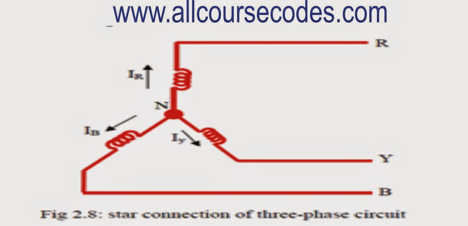
Fig 2.8: star connection of three-phase circuit
Consider fig 2.8.
Let IR = current flowing through the red phaseIY = current flowing through the yellow phase and
IB = current flowing through the blue phase
IR, IY and IB are called phase current (Iph). It is seen that each of the phase currents is equal to the current flowing through the respective lines. Thus, the current flowing through the respective lines is known as the line current (IL)
Hence, in star connection, line current = phase current.
- IL = Iph (2.4) 2.7.3 Line currents and phase currents in a delta connected windings

Fig 2.9 Delta connection of a three phase circuit

Fig 2.10 Phasor diagram of a delta connection of a three phase circuit
Consider the delta connection of a three phase circuit shown in fig 2.9. It phasor diagram is as shown in fig 2.10. To obtain the line currents we proceed as under: Let I1 = IR – IB
I2 = IY - IR
I3 = IB - IY
I1, I2 and I3 are called line currents
Line current I1 is also found by compounding IR and IB reversed as shown in fig 2.10. Its value is given by diagonal of fig 2.10. The parallelogram of fig 2.10 is as shown in fig 2.11.

Fig 2.11: parallelogram of fig 2.10 |
From fig 2.11,
Ox = ½ I1 (2.5)
Also, ox = IB cos300 (2.6)
From equation (2.6) and (2.6), ½ I1 = √3/2 IB If IR = IY = IB = phase current (Iph), then
Current in line no.1 is I1 = √3Iph Current in line no.2 is I2 = √3Iph and
Current in line no.3 is I3 = √3 Iph Since all the line currents are equal in magnitude, i.e I1 = I2 = I3 = IL - IL = √3Iph (2.7)
2.7.4 Line voltages and phase voltages in a delta connected windings It is seen from fig 2.9 that there is only one phase winding completely included between any pair of terminals. Hence, in delta connection, the voltage between any pair of lines is equal to the phase voltage of the phase winding connected between the two lines considered. Hence, for a balanced system, VRY = VYB = VBR = line voltage VL. Then, it is seen that
VL = Vph (2.8)
Social Plugin